The second step to my steamboat was to think about a boiler. Buying a boiler was to expensive for me. And as usual you have to redesign a bought boiler to fit your needs. This is much work too. First I thought of a Scotch Type vertical fire tube boiler. But after some calculations it becomes heavier and heavier ( Maybe my fault of calculation?)
In some publications I had read from the easy to build two and tree drum water tube boiler. But if you want to build one there are many small problems. Very often I wondered how to weld all the steam tubes to the mud and steam drum! Some people are using taped joints (not allowed in the fire area in germany). Others are rolling some copper tubes into steel drums. I don't know how to do this and it is hard to place the rolling tool in the small mud drums.
The most important thing of a boiler is to get a maximum of heating surface in a minimum of boiler volume (But what I am telling YOU this). Finally I chose a water tube boiler design known as the Robert's, Clark or Almy Type with one steam drum and two mud drums.
The first goal was to guarantee the best welding conditions. As second goal I wanted a fire box for long flaming fuel as coal and wood. At last I wanted small dimensions, low weight and deep center point. My design result you can see on the next three drawings.
First you will see the steam drum (d = 280 mm / 11") and the two mud drums (d = 108 mm / 4.25"). The mud drums are connected to the steam drums by four downcombers (d = 54 mm / 2.13"), two on each end. The proportion of the cross section from the downcombers to the steam pipes is 1 : 2,5. For stabilization of the boiler and better water circulation the mud drums are connected additionally at each end with one tube d = 33,8 mm / 1.33" (not shown in this drawing).
To get a good space for welding on the drums I choose steam pipes with the relative big diameter of 33,8 mm / 1.33". So I only needed 28 pipes to get a surface of 4 m² / 43 sp ft of heating surface (Total length of steam pipes 38m / 11.6 ft ) and only 56 welding seams for this. Not only Resulting from this pipe diameter I got a low-water-content from 58 l / 15.3 gal by a steam volume of 33 l / 8.7 gal. This should be good for a smooth behave of the boiler.
Around the pressure body I will build a construction of steel cheat metal with insulation and may be a wood legging (blue hatched). To separate the fire from the mud drums I will place some fire clay bricks around the fire great (blue crossed). So I will prevent the mud drums from damages resulting of the fire and the fire poke. The actual design of the housing and the great I will fix now, after having the ready welded boiler in my shop. Does any one of you have some recommendations about this?
In a water tube boiler on one hand you have to catch the radiation heat of the fire an on the other hand you want to have enough space for welding the steam pipes into the drums. So I placed two rows of pipes on the drums. One row are the s-curved "Robert's Type" tubes and the others are the L-curved "Radow-Type" :-) tubes. The 33,8 mm / 1.33" pipes in each row are placed with 44 mm / 1.73" space. So the direct radiation of the fire can "see" the outer housing only through a gap of 5,1 mm / 0.20" between each pipe.
The three drums are sealed with flanges. It was some work to produce them, but now I have a maximum of inspection and cleaning possibilities and later I can place some additional valves in the heavy flange plates without working on the pressure body.
The third drawing shows the boiler in an additional bird's view. Here the steam pipes are only indicated as green lines. The steam goes through the nine howls from the steam drum into the steam dome (d = 159 mm / 6.25") which is located in the funnel. From the dome the steam branches to the main steam line and the auxiliary steam line to the stern (left). Additional you can see the blower and whistle line branching to the top (left). At the bow side (right) you will find the two blow off lines branching directly from the steam drum to the top. From the blow of valves this lines will go to the funnel and end on its top.
The boiler strength was calculated in order to fulfill the german Steam Boiler Order (Dampfkesselverordnung). Here you can find all necessary calculation orders. As boiler material I used a stainless steal called 1.4571 in the german DIN code (X 6 CrNiMoTi 17 12 2 it's a '316 Ti' type). This is a material with good warm water characteristics. It is t is corrosions and acid resistant. You can buy it for a reasonable price and can find fittings in the same material easily. At least my friend is able to weld this steel because he is doing this the whole day as a boiler welder for beer and food containing tanks.
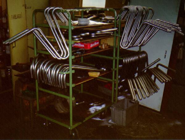
What happens if you are meeting your steam boat friend monthly on a regular pup meeting of railway mans? You will decide to build three boilers at once! Of course, it would be better to build one prototype first - but in the first euphoria we had banded the necessary 84 pipes in 6 weeks. First we had some problems with this. But after making a stencil for the two radius ( r = 65 mm / 2.55" and r = 120 mm / 4.72" ; middle of the tube) and filling the tubes with sand, we did it on an ordinary hand driven hydraulics bending device (10 t ~ 10 long ton).
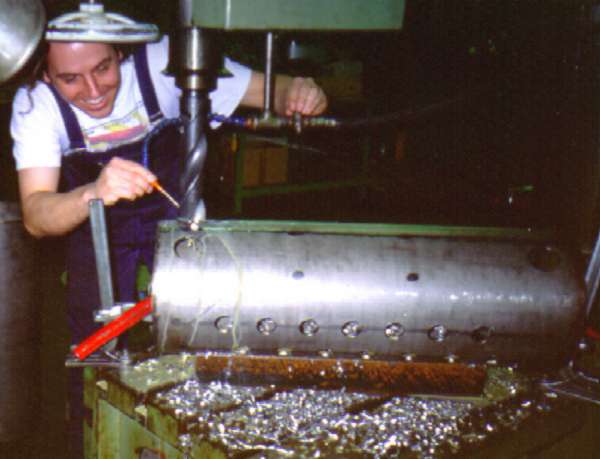
Also at drilling the steam pipe holes into the drums we could use the equipment of my friend Harry Richters little company. For me it was a new experience to use the diameter 58 mm / 2,28" drill for the downcombers after drilling only 8 mm / 0.31" in advance. I normally ever - except on photos - wearing safety glasses!
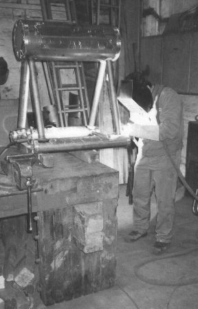
After preparing all parts I brought them to my friend the welder. On this picture you can see him welding the downcombers into the drums. After aligning the parts, he had to close all wholes with a metallic tape. Then he filled the boiler with a protective gas. So the weld seam was protected by gas from inside and outside. This guarantees a good seam quality. A construction with 4 downcombers is much easier to assemble and provides the boiler with higher strength than one with 2 downcombers.
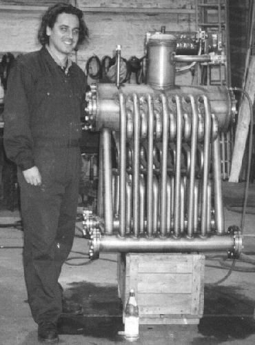
Here you can see me the proud designer and parts preparing men admiring the superb seam quality. No problems with the 80 seams after a first leak test with 16 bar / 232 psi. It's fun to see the boiler the first time what you have designed 2-dimensional on paper/computer.
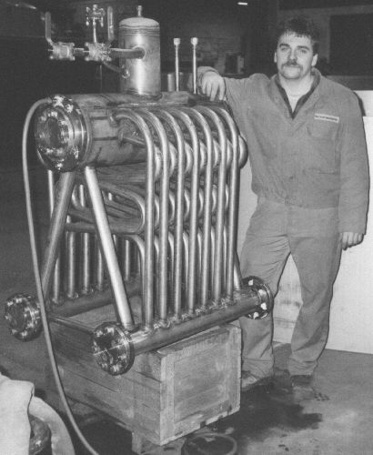
The legitimate proud welder Frank and his work piece. Please try to imagine how to weld all this steam pipes. He first fastened all pipes in a pipe row and in a second operation he closed one seam after an other on each drum. So he 'took' the heat from one seam to the next.
On this photo you can imagine the advantages of the banded tubes. If they will be heated by the fire they can act like a spring, preventing the main structure from the forces caused by head expansion. Also you can see the big fire box for fuel with long flames. In the thick flange of the steam drum you can see some plugs. They are for connecting the gage, the water gage, the feeding line and the foam drain line.
Now the boiler is back in my shop and I have to design and to build the housing and the great. Does any one of you can supply me with some hints concerning this part of work? Do you have some suggesting from your experience? For example: How wide should the fire door be? What type of insulation are you using? How thick should this be? ...