Mildenberg 03. May 2007
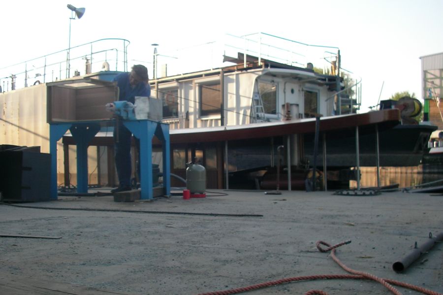
Emma is already in the water, but a lot of work still needs to be done on the pontoon one day before departure. The bench for the 'grease Jack' is being made to fit. The finished emergency steam exhaust pipe is already lying on the floor and must be used if the condensation system installed in the winter does not work in its first test.
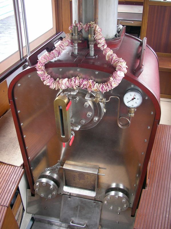
My daughter Rebecca was also busy before departure. As a lucky charm for Emma, she spent two hours threading scattered flowers onto a thread. The flower wreath has now dried and is still accompanying Emma on her journey.
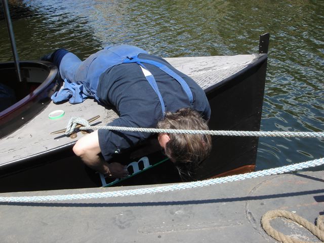
We hadn't yet celebrated Emma's ship launching, but to appease the water police, I quickly stuck the letters cut out with nail scissors to the bow.
After almost 19 months of lying in the hall, the engine is finally heating up again and the machine is turning. 20 minutes of gymnastics on the jetty should be enough. We now have 6 days to drive the 65 km to Mildenberg and back. As my workshop is 190 km away in Leipzig, we can set off now, as if there were a problem we would only be able to use the adequate on-board resources or rely on outside help.
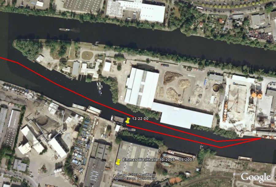
Migges brought his GPS with him, with which we can record the entire route and determine the speed at the same time. The visualization in the free Google Earth is of course great - we set off at 1:22 p.m. and after a short loop we head off towards Mildenberg.
PS: In 2007, something like this was still a small sensation - the iPhone 1 only came onto the market in September 2007!
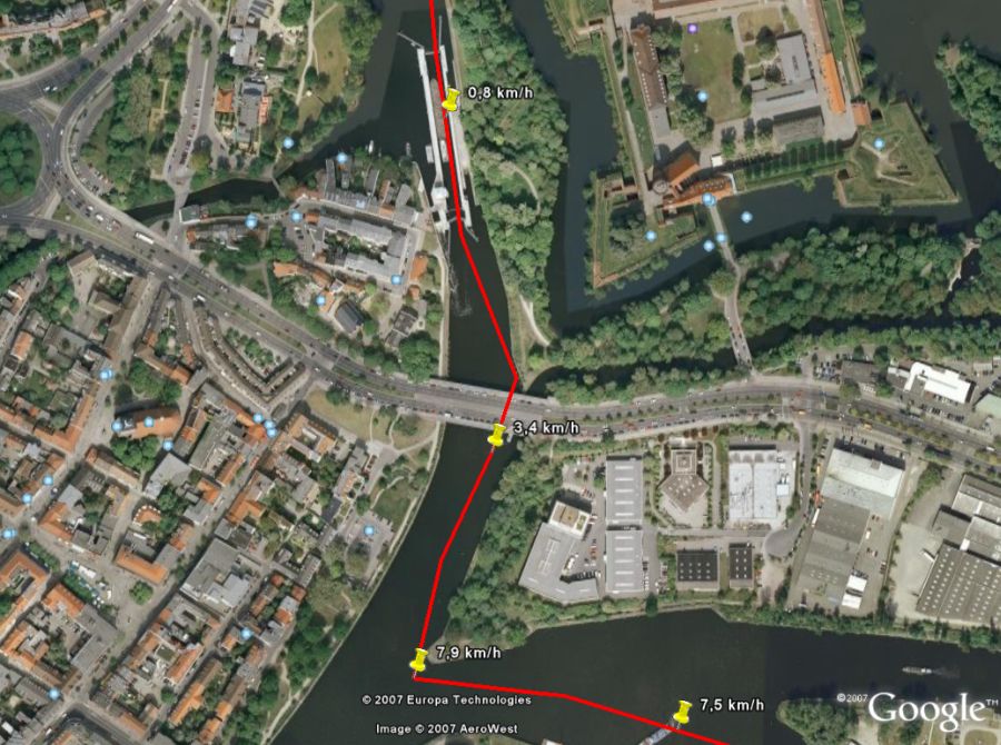
What I find particularly impressive about GPS technology is the accuracy of the system, which of course only becomes really tangible in the Google Earth display (of course, in 2007 this was only possible at home on the computer!). We come from the bottom right and after a short wait we drive through the Spandau lock at 52.5407° north latitude and 13.209° east longitude.
I had so much fun evaluating the travel data that I immediately bought a GPS. If you would like to find out more about it, you can find a program I wrote for processing and documenting such geodata on my GPS page.
We passed through the Spandau lock unscathed.
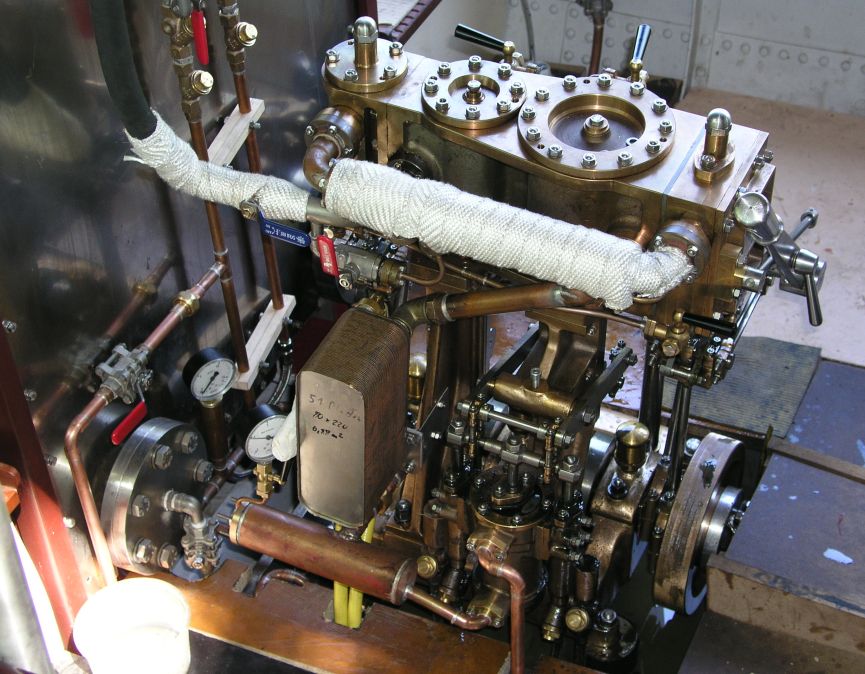
In the winter of 2006/07 I converted the machine from exhaust operation to inboard condensation. From the low-pressure cylinder (large cover on the right) the uninsulated d=28 mm exhaust steam line runs with a gradient to the plate condenser (rectangular box on the left on the stand of the high-pressure cylinder). The condensate runs from the bottom of the condenser into the transverse d=54 mm collector. From here the condensate runs again with a gradient to the vacuum pump on the ND stand. At the top of the pump the condensate is then drained to the cistern (hot well) via a D=15 mm copper line.
The condenser is supplied with and drained of the necessary cooling water via the two yellow hoses.
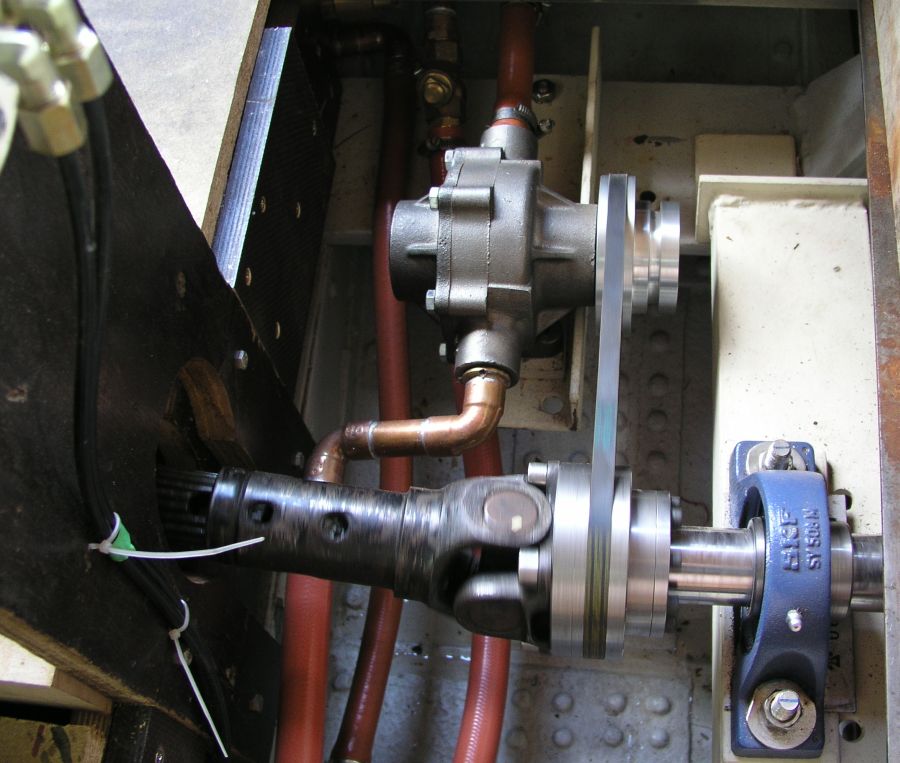
While with external cooling the cooling water can flow around the steam-flowing cooling pipes on its own, the inboard condensation requires a cooling water pump.
I used a HYPRO roller pump series 7560 in SilverCast design with 8 rollers. It is driven 1:1 by the propeller shaft via a V-belt.
While with external cooling the cooling water can flow around the steam-flowing cooling pipes on its own, inboard condensation requires a cooling water pump. I used a HYPRO roller pump series 7560 in SilverCast design with 8 rollers. It is driven by a V-belt 1:1.
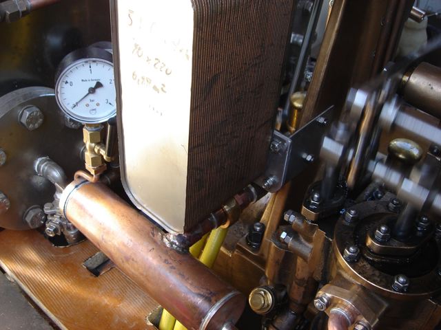
Here is another close-up of the plate cooler. 51 stainless steel plates are soldered on top of each other with a total cooling surface of approx. 0.88 m2. Such heat exchangers are used, for example, in district heating systems to generate hot water and can be bought on eBay for around 50 - 100 EUR.
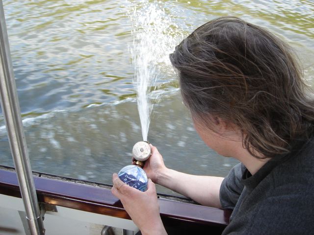
If you haven't noticed, the vacuum gauge shows something under -0.9 bar! That is a sensational vacuum that I have never seen on a steamboat or steamship before. If you don't believe it, you are welcome to bring your manometer and have it installed for me.
Due to the constant gradient in the system from the exhaust of the low-pressure cylinder to the vacuum pump, this vacuum is permanently available from the first revolutions of the machine. Due to the proportionality of the cooling water quantity to the steam quantity ensured by the belt drive, the condensate temperature is 45-50 °C regardless of the speed. These are two major advantages over outboard condensation.
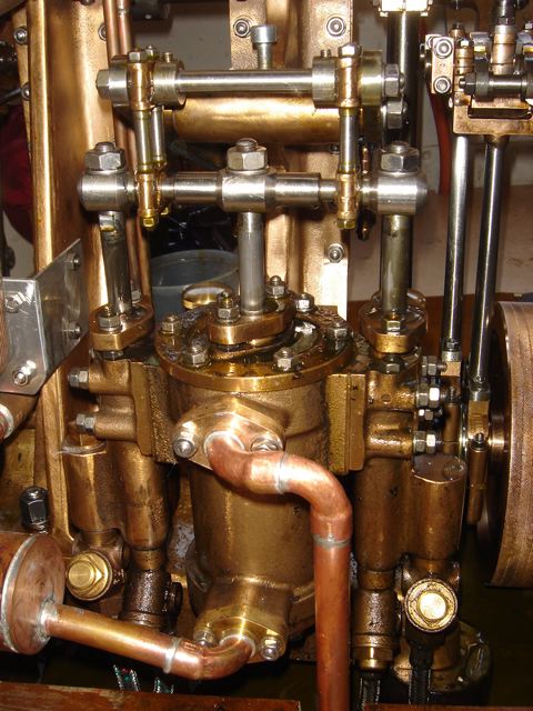
Here is the pump unit mounted on the ND stand in detail. In the middle is the vacuum pump with the intake at the bottom and the outlet at the top. The plunger pumps for feeding the boiler are on the left and right. All three pumps are driven by the ND crosshead via levers.
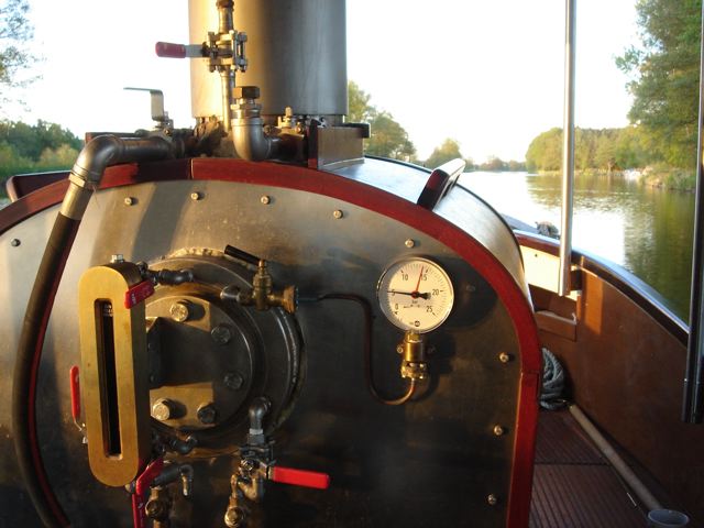
On this day, 5 - 6 bar boiler pressure has been found to be the optimum for a cruising speed of 8-9 km/h. The steam supply hardly needs to be throttled any more, so there are no losses. With the good vacuum, the low-pressure cylinder also has enough to work with. The pressure gauge in the receiver will soon be retrofitted so that this feeling can be backed up with numbers.
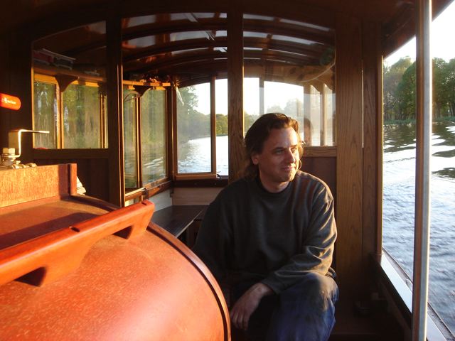
We have passed the last lock and are enjoying the evening atmosphere. The day went well and there were no technical problems in the first 40 km.